
Industrial automation environments increasingly rely on dense computing architectures to execute real-time control algorithms. As Programmable Logic Controllers (PLCs), Variable Frequency Drives (VFDs), and distributed I/O blocks migrate toward higher clock speeds and sub-micron semiconductor fabrication nodes, their operational voltage margins shrink dramatically. Modern industrial microprocessors operate on internal logic rails as low as 1.8V to 3.3V DC, making their silicon junctions highly vulnerable to physical stress.
While legacy electromechanical relays could absorb high-energy spikes without immediate failure, modern integrated circuits experience dielectric breakdown when exposed to microsecond-level overvoltages.
A voltage deviation lasting less than 5 microseconds can rupture silicon gate oxide layers, corrupt memory registers, or cause latch-up conditions. For automated process plants, these transient events cause intermittent communication dropouts, corrupted fieldbus packets, and unexplained processor halts.
Safeguarding sensitive automation infrastructure requires dedicated transient suppression architectures that divert surge currents before they breach control enclosures.
Engineering Effective Surge Protection Architecture
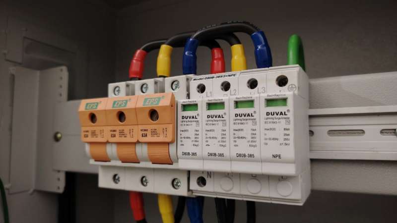
To effectively clamp voltage spikes before they reach sensitive logic boards, facility engineers must implement a cascaded defense strategy. This requires installing high-performance surge protection devices (SPDs) from specialized engineering manufacturers like LSP at both the main entry point (Type 1) and directly inside the control cabinet (Type 2 or Type 3). Modern industrial SPDs utilize advanced Metal Oxide Varistors (MOVs) to safely divert excess current to the ground, operating in nanoseconds to ensure uninterrupted plant operations.
Relying on a single protective element at the service entrance leaves localized electronics exposed to internally generated high-frequency disturbances.
The Principle of Cascaded Protection
A robust industrial facility employs a coordinated, multi-stage overvoltage suppression topology. This layered framework systematically attenuates energy levels across power distribution boundaries:
- Primary Service Entrance (Type 1 / Class I): Positioned at the main facility switchboard, Type 1 SPDs handle high-energy impulses characterized by the 10/350 µs waveform, typically associated with direct lightning strikes or heavy utility load transfers.
- Secondary Branch Distribution (Type 2 / Class II): Installed at Motor Control Centers (MCCs) and sub-distribution panels, Type 2 SPDs clamp residual voltages using an 8/20 µs current waveform, dissipating switching surges and clearing upstream let-through energy.
- Point-of-Use Control Cabinets (Type 3 / Class III): Mounted directly on the DIN rail inside control enclosures, Type 3 devices provide fine-tuned suppression adjacent to 24V DC switch-mode power supplies (SMPS) and sensitive analog I/O cards.
- Signal and Data Line Protection: Dedicated terminal-block suppressors must isolate RS-485, Industrial Ethernet, and 4–20 mA current loops from common-mode capacitive coupling.
Selecting the Right SPD Specifications
Specifying an SPD requires matching component electrical ratings with the specific power environment and target hardware tolerance curves. Mismatched ratings leave equipment unprotected or lead to premature varistor failure:
- Maximum Continuous Operating Voltage (Uc / MCOV): The SPD’s MCOV must exceed nominal line voltage by at least 15% to 25% to prevent continuous thermal conduction during normal utility grid swells.
- Voltage Protection Level (Up) and Clamping Voltage: The Up metric defines the peak let-through voltage delivered to downstream loads during a discharge event; it must remain well below the impulse withstand voltage (Uw) of downstream PLCs, typically rated under 1.5 kV.
- Nominal Discharge Current (In): Control cabinet Type 2 units must sustain a minimum In rating of 20 kA (8/20 µs) for repeated operational cycles without parameter drift.
- Response Time (tA): Fast-acting Metal Oxide Varistors (MOVs) achieve response times under 25 nanoseconds, while secondary DC loops incorporate Silicon Avalanche Diodes (SAD) responding in less than 1 picosecond.
- Integral Thermal Disconnects: High-grade SPDs feature internal mechanical micro-switches and visual status flags that isolate degraded varistor modules during thermal runaway, accompanied by dry contacts for remote PLC alarm monitoring.
Primary Sources of Transient Voltage Surges in Manufacturing
Industrial facilities operate dynamic electrical networks where heavy inductive and capacitive equipment continually cycles on and off. While external meteorological phenomena receive substantial attention, operational data demonstrates that most damaging transients originate within facility boundaries.
Differentiating internal electrical noise from external disturbances allows engineers to place protective components where risk factors are concentrated.
Internal Switching Overvoltages
Industrial power quality audits indicate that approximately 80% of transient overvoltages are generated internally by inductive load manipulation and power electronics switching.
These microsecond anomalies recur hundreds of times per shift, degrading components through cumulative dielectric stress:
- Inductive Kickback from Coils and Relays: De-energizing large contactor coils, industrial solenoids, and magnetic brakes produces back-electromotive forces reaching several thousand volts if unsuppressed.
- Variable Frequency Drive (VFD) Inverter Harmonics: High-frequency pulse-width modulation (PWM) switching using insulated-gate bipolar transistors (IGBTs) creates steep voltage rise times (dV/dt), reflecting transient wave reflections along motor feeder cables.
- Power Factor Correction Capacitor Banks: Switching bulk capacitor banks generates high-energy oscillatory transients that propagate across branch panels into low-voltage DC power supplies.
- Welding and Arc Furnaces: Dynamic resistance changes in automated robotic welders create localized ground potential rises and high-amplitude voltage notches across adjacent branch circuits.
External Threats: Grid Fluctuations and Lightning
External disturbances, while less frequent than internal switching events, introduce destructive energy levels that destroy unprotected electronic components.
External transient vectors penetrate facilities through multiple entry points:
- Indirect Lightning Strikes: Cloud-to-ground strikes several hundred meters away induce substantial electromagnetic pulses (LEMP) into buried electrical conduits and structural steel framing.
- Utility Grid Switching: Substation capacitor switching, transformer tap changing, and automated transmission line re-closer operations send high-energy traveling waves into industrial service drops.
- Ground Potential Rise (GPR): Massive lightning discharge currents entering earth grounding grids create instantaneous voltage gradients between separate sub-station grounding rods, driving return surge currents backward through grounded shield cables.
Compliance with International Electrical Standards
When integrating transient voltage suppression into industrial control cabinets, it is non-negotiable to follow established engineering frameworks. System integrators must ensure that their chosen protective devices comply with international benchmarks, such as the IEC 61643 series or UL 1449. Understanding the fundamental mechanics of a surge protector and its testing standards ensures that the selected components can handle the specific short-circuit current ratings of the facility without risking catastrophic failure.
Standardized design methodologies eliminate guesswork, guaranteeing safety, insurance compliance, and long-term hardware reliability.
- IEC 61643-11 & IEC 61643-21: Defines performance criteria, testing methodologies, and safety verification for surge protective devices connected to low-voltage power distribution networks and communication lines.
- UL 1449 5th Edition: The governing standard in North America evaluating Short-Circuit Current Ratings (SCCR), Nominal Discharge Current testing, and catastrophic failure containment under overvoltage runaway.
- NFPA 79 (Electrical Standard for Industrial Machinery): Mandates that industrial machines containing sensitive logic circuitry must incorporate dedicated surge protection to prevent safety circuit lockouts.
- IEEE C62.41.2: Categorizes surge environments into Location Categories A, B, and C, dictating the stress amplitudes required to validate industrial electrical assemblies.
Conclusion: Proactive ROI in Power Quality Management
Transient overvoltage mitigation is an essential element of modern electrical engineering, not an optional hardware add-on. As smart factories accelerate their deployment of connected sensors, edge computing devices, and precision microprocessors, the financial impact of unsuppressed voltage anomalies grows exponentially.
A single transient event can destroy a multi-axis motion controller, scramble industrial network switches, or force hours of unplanned assembly line downtime. Compared to the thousands of dollars incurred during a single hour of facility outage, investing in coordinated, multi-stage DIN-rail surge suppression offers rapid, measurable return on investment.
Electrical engineers, panel builders, and plant operations teams must audit their incoming power distributions and control cabinet topologies. Designing a coordinated surge suppression architecture protects core capital assets, sustains fieldbus communications, and maintains operational uptime across manufacturing facilities.